Just a few years ago, manufacturers of innovative or specialized devices who wanted to implement their projects faced a dilemma. Wanting to produce the first series of devices from plastic, they had the choice of either using costly injection molding or other technologies that often did not meet the strength or aesthetic requirements.
However, the appearance of Multi Jet Fusion 3D printing technology on the market in 2016 showed new hope for companies with such needs.
Now, 9 years after the premiere of the first industrial MJF printers, we already know that 3D printing can be an excellent alternative to injection molding, allowing you to obtain isotropic parts with high durability.
In the article, we will tell you about the technology itself, as well as the specific procedures that designers can use to create extremely durable, strong parts using MJF technology.
Introduction to MJF Technology
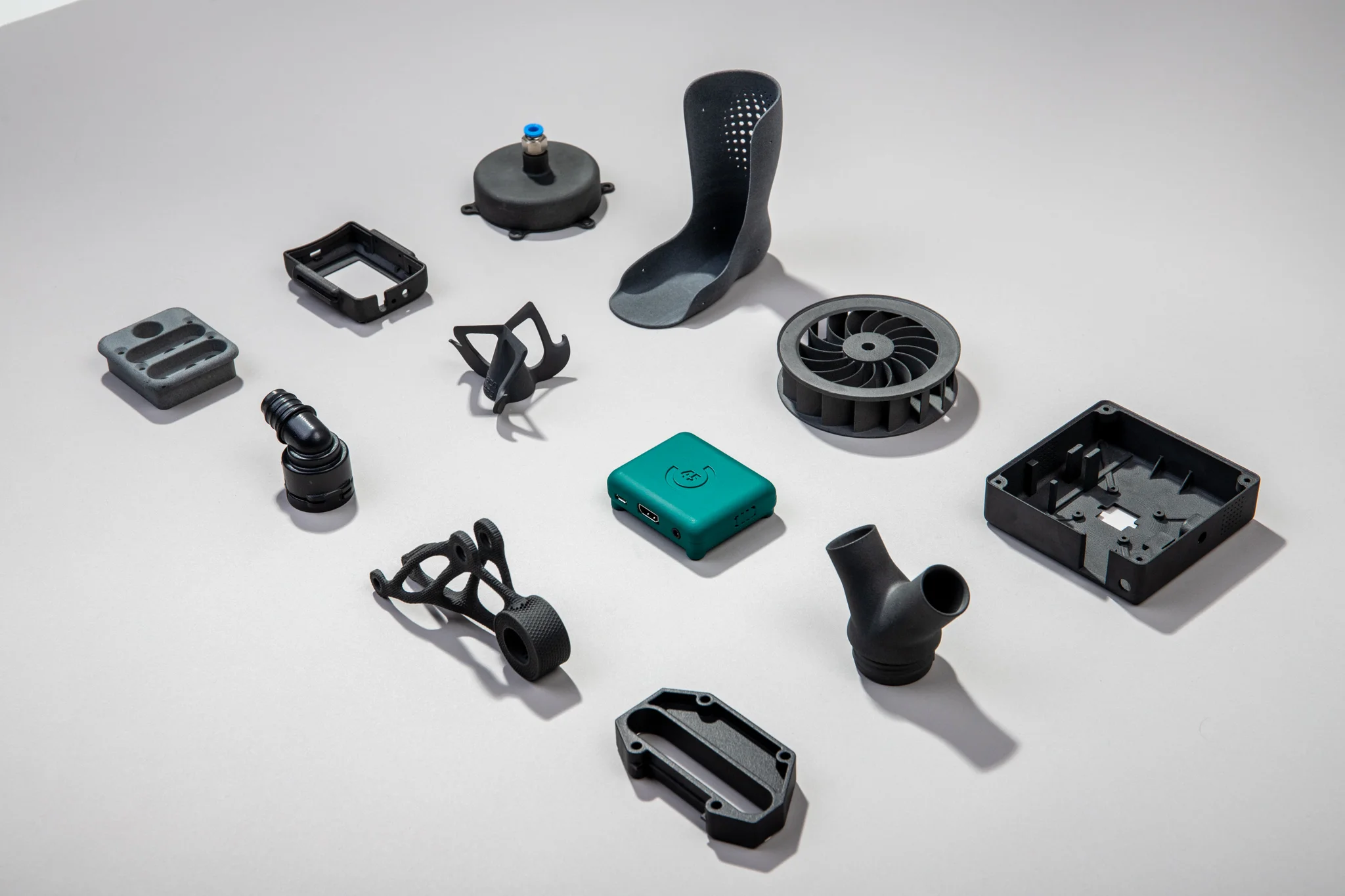
The first HP Multi Jet Fusion (MJF) devices appeared on the market relatively recently, only in 2016. These industrial 3D printers use plastics (mainly polyamide PA12) with high mechanical parameters and can produce even several hundred parts in a single, several-hour process.
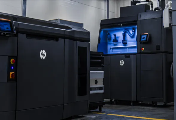
Although this technology qualifies for the broad category of “3D printing,” its operating principle differs significantly from the commonly known FDM (Fused Deposition Modeling). Instead of filament, elements are created by precisely sintering powder in a printing chamber.
So what does this mean specifically for manufactured parts? Here are some key facts.
MJF printed PA12 parts achieve tensile strength of ~45–50 MPa, which makes them comparable to many traditionally molded materials.
Importantly, the mechanical properties of MJF are almost isotropic– the strength in the Z axis is similar to the strength in the XY plane (e.g., 49 MPa vs 45 MPa).
This gives designers a lot of freedom and doesn’t require them to compensate for the material’s anisotropy to such an extent as with FDM.
However, many design techniques allow for increased mechanical strength MJF parts without increasing the weight. Below, we present key guidelines and good design practices for MJF technology in PA12 material, supported by research results and expert opinions.
Material Properties and the Influence of Print Orientation
The characteristics of the material have a quite obvious influence on the strength parameters, but in the case of MJF technology, the influence of the arrangement in the chamber and the printing orientation is slightly less obvious.
Due to the specificity of the MJF process, the mechanical properties are largely uniform in different directions. Research shows that PA12 samples printed in vertical orientation (Z-axis) achieve tensile strength similar to horizontal samples.
This means that print orientation does not significantly affect the breaking strength – this is a significant advantage of MJF over technologies such as FDM or SLS.
The influence of orientation is revealed in other parameters, such as elongation at break. The parts printed vertically are more fragile– their elongation at break can be twice as small (e.g. ~9% in the Z axis vs ~17% in the XY axis).
The layers applied in the process can create small interlayer weaknesses, which reduce ductility. Therefore, for components subjected to impact or fatigue, an orientation in which the main loads act in the plane of the layers (XY) is recommended.
Selecting the print orientation is, therefore, an important tool for increasing endurance. The general rule is orienting elongated, slender elements in the horizontal plane (XY). Our experience shows that long and thin parts should be printed in landscape orientation.
This avoids a situation where the part is “chopped” into multiple layers along its length, which could increase the risk of breakage along the edges of the layers.
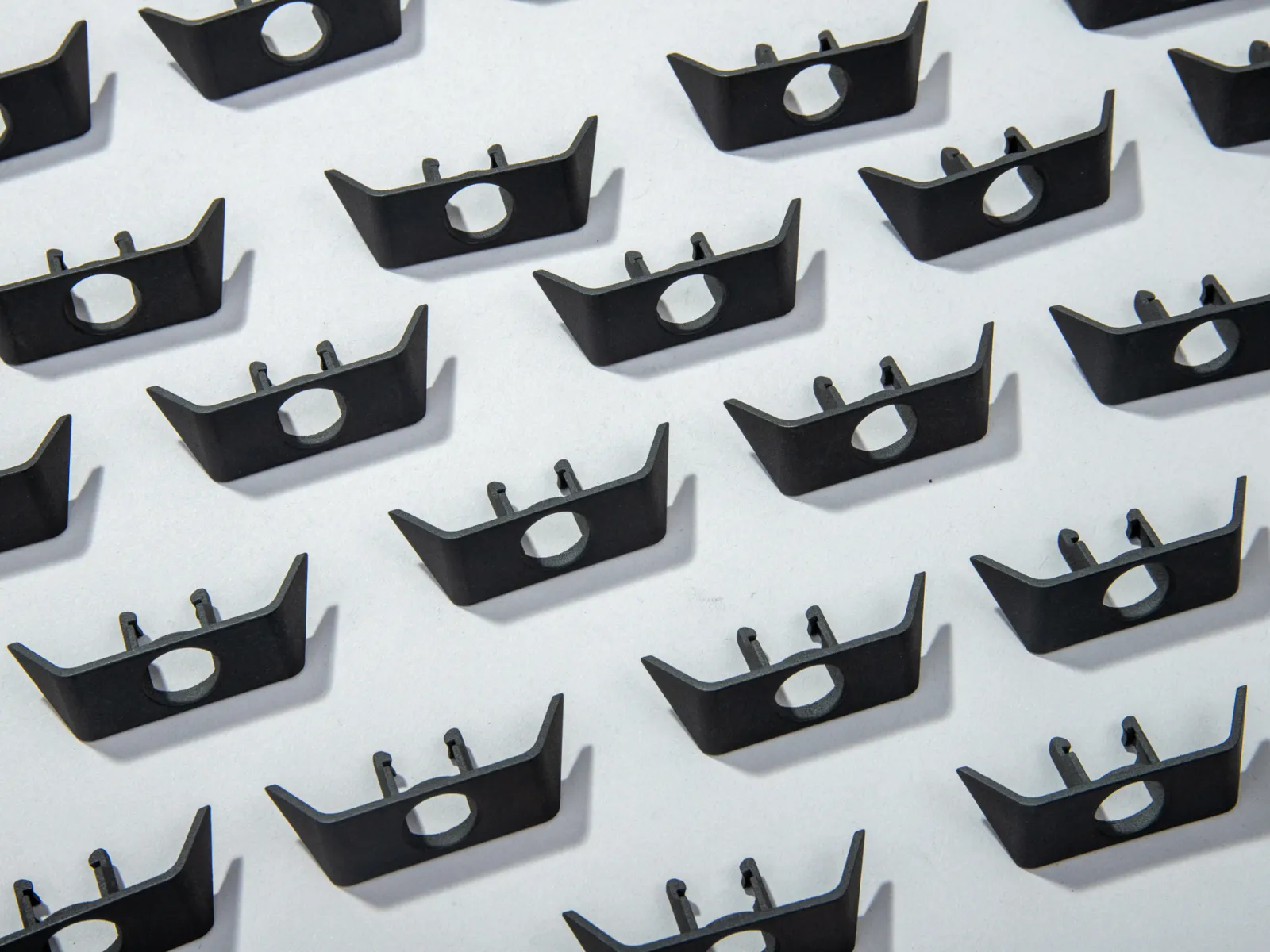
Small structural elements, such as pins, spring clips, or latches, should be designed to be printed in a horizontal position– then the layers run along the length of the element, not across it, which increases its resistance to bending and shearing.
Additionally, orientation affects surface quality. Critical surfaces that are subject to friction or require smoothness are better placed parallel to the platform (in the XY plane) to avoid the effect of layer stepping.
In summary, the isotropic properties of MJF give us great flexibility in orienting the model for maximum strength and quality, but it is recommended to: important load-bearing elements and slender parts should be arranged horizontally, and the orientation of critical areas should be adjusted to the directions of the main loads.
Thanks to our experience, in most cases, we can judge for ourselves what position in the chamber will be most suitable for a given element. However, it is always helpful to better understand the role of each element and how exactly it is to be used. When discussing needs with clients, we always ask them to mark any critical areas in the design so that we can ensure they are positioned correctly during printing.
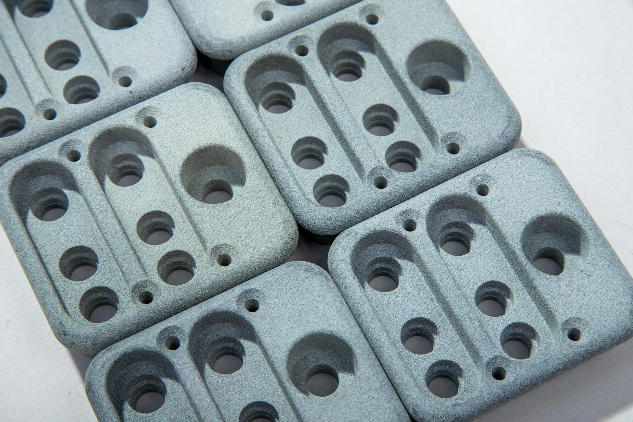
As for the material itself, polyamide PA12 is characterized by high strength, impact resistance, and moderate stiffness, and the parts are dense and practically non-porous (density approx. 1.01 g/cm³).
Minimum wall thickness and construction
One of the simplest ways to improve strength is to ensure the proper thickness and shape of part walls. Too thin walls are susceptible to deformation during printing (e.g., bulges, warps) and may be mechanically weak.
It is recommended that the minimum wall thickness for PA12 MJF is at least 1.0 mm. Walls thinner than ~0.5–0.8 mm may not sinter completely and may deform easily.
In the case of very small elements, ~0.5 mm is allowed, but with a limitation on the length of such a thin section and avoiding orientation parallel to the Z axis.
It should be remembered that although MJF provides relatively isotropic properties, the thinnest and most delicate sections of the structure fare better when they are not laid vertically layer by layer.
Too thick walls and massive blocks are also not desirable. Not only do they increase mass and cost, but they can also cause printing defects. In powder sintering processes, thick cross-sections accumulate heat, which can lead to local shrinkage, deformation, and the formation of surface defects (e.g., depressions, rough areas).
It is therefore recommended to avoid monolithic blocks of material > 20 mm thick where it is not needed. A better approach is slimming down massive elements by hollowing out internal structures. For example, when a project requires a large volume, the model can be hollowed out, leaving walls 2-3 mm thick and adding service holes (min. Ø2-3 mm) for the removal of unsintered powder from the inside. This approach reduces mass and the risk of defects (e.g., collapse) without compromising the strength of the external surfaces.
To ensure rigidity and strength, it is not always necessary to simply thicken all the walls– this would increase the mass in a suboptimal way. Instead, we use local reinforcements, such as ribs, which stiffen critical areas with minimal added material. Design guidelines indicate that if a thin wall does not meet the strength requirements, it is better to add reinforcing ribs or rounded reinforcements (like corner filleting) than to uniformly increase its thickness.
Rib – a key project optimization procedure
A rib is a thin wall perpendicular to the surface that significantly increases the bending resistance of a large flat surface while adding virtually no mass. The material added this way is minimal compared to adding the same thickness across the entire surface.)
Functional ribs are especially useful for reinforcing covers, casings, and flat panels that would otherwise bend under load. Strength simulations indicate that adding ribs to a flat plate significantly increases its stiffness and resistance to deflection.
However, it is worth designing the ribs with caution – too dense a network of ribs under a large plate may make it difficult for the material to shrink freely when cooling and paradoxically increase the risk of deformation (warping).
PA12 material tends to warp large, flat areas as it cools, so it is best to avoid designing very large flat surfaces with dimensions comparable to the print area. If this cannot be avoided, it is worth considering to slightly bend the surface (giving it a minimal arc) or dividing it into smaller structural segments to disperse shrinkage stresses.
To sum up, maintaining optimal wall thickness and avoiding extremes is key, and you can find this golden mean by following two tips:
- Reinforce walls that are too thin locally (with ribs, thickening at the edges, stiffening the corners)
- The walls are too thick and the blocks are massive, revealing a cavity or internal structure. Such a strategy will provide high strength where you need it, without generating unnecessary bulk or printing defects.
Smooth transitions and avoiding stress concentrations
Classical knowledge of strength of materials says that the geometry of the part strongly influences the local stresses. Sharp bends in the shape are particularly dangerous –karby (e.g. sharp internal corners, sudden changes in cross-section, sharp edges of holes) – which cause stress concentrations.
A part designed without taking that into account may prematurely break at the sharp notch, even though the overall strength of the material is high. Therefore, the key principle is avoiding abrupt changes in cross-section and sharp angles in load-bearing areas of the structure. Instead, we introduce smooth transitions– fillets (chamfers or fillets) – which distribute the stresses over a larger area.
Rounding the inner edges (filleting) is particularly important in 3D printing because it not only improves strength but also makes the printing process easier. Adding a radius at the point where two walls join eliminates the unfavorable “reentrant corner” and acts as a kind of stress disperser.
Simulations and analyses clearly indicate: the larger the fillet radius, the lower the stress concentration factor. In the extreme case, a sharp corner (radius -> 0) generates theoretically infinitely large stresses at the edge, which in practice means crack initiation even at a small load.
It is therefore recommended to enter as much as possible internal filleting wherever loads are concentrated – for example, at the base of protruding supports, at the corners of internal pockets, around holes and recesses.
What’s more, roundings are more beneficial for strength than chamfers, as the arc distributes stresses most evenly. Therefore, in parts exposed to dynamic or fatigue loads, radii are preferred, not just edge chamfers.
In addition to the inner edges, it is also worth rounding off the outer sharp edges of elements subject to stress to avoid jamming and initiating cracks from the surface. In practice, MJF printing and so the sharpest edges of the model are minimally rounded due to the powder sintering process, so the designer can consciously take this into account and explicitly design smooth transitions.
Avoiding stress concentration also involves the arrangement of holes, recesses, and other features. Don’t design a hole too close to the edge of a part or too close to another hole. There should be some material between them that acts as a “bridge” to transfer forces.
Engineering rules suggest spacing of at least the hole diameter from the edge of the hole to the outer edge of the member to avoid weak spots. If the hole is to be used for fastening and transferring loads (e.g. a hole for a bolt, pin), it is good practice to reinforce it with a collar or local thickening around so that the stresses from the screw contact are distributed in the material. In MJF printing, such build-ups at the holes can be seamlessly integrated, which will increase local strength without a large impact on mass.
To sum up, designing to minimize stress concentration comes down to a simple rule: soft designs, not sharp. Where possible, we replace sharp angles with curves, edges with fillets, and abrupt changes in cross-section with gradual ones. As a result, the part has no “sensitive points” and is much more mechanically resistant under real load conditions.
Grid structures and lightweight yet durable construction
To increase endurance without significant weight gain, the key is to properly distribute the material in the part. 3D printing provides unique possibilities for creating internal structures and geometry that are impossible to achieve traditionally, allowing for an optimized strength-to-weight ratio. The two main approaches are lattice structures inside the part and topological optimization entire body.
Lattice structures consist of replacing part of the solid material with an openwork mesh of internal ribs or cells (e.g., in the form of hexagons, gyroid structures, rod networks, etc.).

In MJF technology, this is particularly attractive because printing does not require additional support of such a grid – unsintered powder supports the elements during construction and can then be poured out. The use of the grid allows for a drastic reduction in the mass of the part while maintaining its skeletal strength.
A well-designed truss can carry loads similar to solid material if the loads are distributed, while at the same time introducing voids where the material does not work. Such treatments significantly reduce weight while maintaining mechanical integrity.
In short, the elements are lighter, cheaper to produce, and just as durable.
How to design appropriate lattice structures?
The most important tip is that the truss rods have been kept to a minimum thickness to ensure strength.
In the case of MJF, rods with a diameter of <0.5 mm may no longer sinter completely or will be brittle. As with walls, a general value of ~0.8–1.0 mm is assumed for truss rods.
By the way, the spacing between truss elements must allow the powder to be removed. Experience has shown that clearance of at least 1 mm is required to allow the unsintered powder to flow out freely or be blown out.
Too dense, fine mesh can trap powder inside, increasing part weight and contaminating such parts. It is therefore recommended to design the grid cells so that the holes between them have a diameter of ≥1 mm.
If necessary, special service holes or thin “chains” can be designed inside the channels to facilitate crumbling and removal of the powder.
Topology Optimization – (Almost) Automated Solution
Topological optimization is a design method in which a computer program (e.g. a generative CAD design module) distributes material in the model in the most efficient way possible, removing material where it is not needed to carry the given loads.
The results are often organic-looking shapes with a ribbed or openwork structure that look “foreign” but fulfill mechanical functions with minimal mass.
Additive printing technologies, such as MJF, can produce such shapes without difficulty (which could not be done with, for example, a CNC milling machine).
Also in this case, the idea of the solution is to reduce material consumption while maintaining strength, leading to lighter, more cost-effective structures. This is an approach that is becoming more widely used in the aerospace, automotive, and wherever“every gram counts”. Due to its operating principle and precision, MJF is the perfect technology for this.
Interestingly, the HP does it too. In-house, the company redesigned the sensor holder in the latex printer, which was previously a massive, milled aluminum block. The use of generative design and MJF PA12 printing allowed for the reduction of the weight of the element by 93% (from 355 g to 23 g) while maintaining the required structural strength.
To sum up, the internal relief structure is one of the most effective ways to achieve a lightweight yet strong part, and MJF technology provides excellent opportunities for this.
Other techniques for strengthening structures
In addition to the main methods discussed above, several additional engineering techniques can improve the strength of parts printed in PA12 using the MJF method, without a large increase in weight.
These include, among others, local geometry thickening and reinforcement, appropriate connecting components, and post-processing parts. Although the latter goes beyond the design changes themselves, it is worth mentioning briefly in this topic.
- Diagonal ribs and corner supports: In places where two surfaces form an angle (e.g. the base of a vertical wall connecting to the ground), adding a small triangular support at the corner (gusset) can significantly increase the bending moment resistance. Such support acts as an additional material preventing the deformation of the right angle. Designers often use this trick, for example, when connecting a column to a base – instead of a sharp angle, they provide a small triangle of material that distributes the stresses from bending the column to a wider zone in the base. In 3D printing, adding such a support does not generate any problem (there is no need to mill undercuts, etc.), and significantly increases resistance to corner breakage.
- Connecting elements: Although MJF allows you to print a complex assembly as a single part, it is sometimes beneficial to divide the structure into modules and then connect them (e.g. with screws or latches). From a strength perspective, separating the elements can allow for better orientation of printing each part separately (each module in an optimal position for loads), and also facilitate the use of reinforcements where they are needed, without increasing the mass of the whole. For example, a large frame-shaped support can be printed as several elements, which we will then screw together – this will avoid certain compromises in the design (e.g. the need for thick supports in a single print). However, it should be remembered that connections (e.g. screws) can become new points of stress concentration or clearance – therefore, if possible, it is preferable to use the consolidation of parts in one print to avoid debilitating mounting interfaces. It also eliminates the need for screws or adhesives, which removes potential weak points (no additional mounting stresses, no corrosion points or play). In other words, modular connection makes sense mainly when it allows for more optimal printing of individual pieces or their subsequent interchangeability, but from a purely strength perspective, a single monolithic part (well designed) will usually be better.
- Design for dynamic loads: If it is known that a part will be subjected to cyclic (fatigue) or impact loading, it is worth considering some specific features in the design. For example, avoid mass concentration at the ends of the long arms– it is better to distribute mass closer to the support point to reduce inertia and dynamic stresses. In MJF printing, for example, you can make an openwork end of the arm (reducing mass at the end) and a more solid base. Integrating elastic (spring) elements directly into the design can also protect critical areas from impact.
All of the above methods can be used together. However, the greatest benefits are achieved through smart design at the CAD stage.
Each new project we undertake only confirms that 3D printing offers unprecedented freedom of design. You can create molds that take into account strength requirements without considering the limitations of conventional machining. As a result, a well-designed additive part can have fewer sensitive areas and better mechanical properties than a “CNC” design. In other words, designing for MJFallows “design to meet requirements, not manufacturing constraints”, which often results in a more durable and at the same time lighter component.
Summary
Optimizing the design for HP Multi Jet Fusion technology in PA12 material opens the way to significantly increasing the strength of the part without unnecessary weight increase.
Key recommendations include:
- ensuring sufficient wall thickness and uniformity (minimum ~1 mm, avoiding sudden changes in thickness),
- Use smart reinforcements such as ribs and smooth curves instead of massive oversizing,
- elimination of sharp edges and other stress concentrators by filleting and grading shapes,
- use of internal structures(trusses, chambers), and generative tools to relieve the structure.
Print orientation in MJF has less impact than in other methods, but it is still worth placing critical elements in an optimal position (long elements horizontally, layers perpendicular to the main stress directions).
We encourage you to read our case studies, in which you will read about how, by optimizing the design, you can reduce the weight of a part by even several dozen percent while maintaining or even improving its strength.
The purely design approach has the advantage that “it costs nothing” in the sense of material. We optimize the distribution of already existing material instead of adding new material. So we achieve better relative strength (per unit weight).
This is especially important in modern engineering, where the goal is lightweight, strong structures. The techniques presented in the above report – from simple geometry changes to advanced optimization algorithms – together constitute a coherent set of tools for the designer.
Thanks to them, PA12 parts using HP MJF technology can achieve strengths that meet the requirements of industrial applications while fully exploiting the potential of additive freedom of form.
As HP itself emphasizes, printing allows you to focus on design that meets requirements, not constraints, resulting in better quality components and mechanical properties.
If you have any more questions about designing for MJF or need to print someting, let us know!